Forum Replies Created
-
AuthorPosts
-
August 18, 2021 at 4:53 pm in reply to: App failed to load. Not sure if this is a software or a hardware problem. #1316
jhendricks
ParticipantGood news! I received an AS7341 yesterday from a Mouser backorder-hail-mary and successfully repaired the spectrometer board (as opposed to the hack-job breakout board I stuffed in there previously.) It would seem that we’re back in business!
Excellent tip on the hotplate btw, I’d never used one before last night. I found it to be incredibly easy and so gentle compared to other methods. Definitely using that going forward.Thanks for the test suggestions, I’ll give that a go today. Thanks for everything really, I am very grateful for your quick and helpful responses.
“You mentioned the TCA9803 was one issue – did the soldering look bad on the original one?”
I’m not really qualified to say, but I did take a close look at the chip with my $30 USB microscope and snapped a few pics before replacing it. Before I replaced it, I ran a razor blade between the pins but it didn’t make any difference. I’ll let Labmaker know the full run-down once I’ve received and inspected the next bioreactor. Yzhang is adamant that he kept control of the power adapter and that it couldn’t have been swapped but weird stuff happens in shared spaces.These pictures look worse than reality. The flux reflects light, making it look like solder.


 August 16, 2021 at 6:47 pm in reply to: App failed to load. Not sure if this is a software or a hardware problem. #1313
jhendricks
ParticipantCorrection: that’s to be expected with outside light streaming in
Last time I tried to edit my post it got deleted somehow, so I’m just gonna do it this way.
August 16, 2021 at 6:43 pm in reply to: App failed to load. Not sure if this is a software or a hardware problem. #1312jhendricks
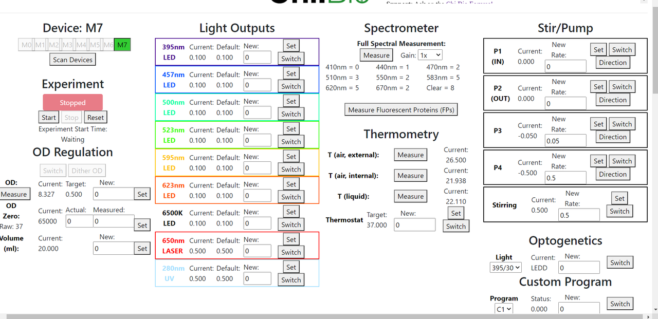
ParticipantHere’s a screenshot of what I’ve been brave enough to try this morning, using the new v1.2 cape. Pumps are pumping, stirrer stirs, laser illuminates, LED’s make their pretty colors, hack-job spectrometer reads, all three temp sensors are talking. OD readings are wacky of course but that’s to be expected without outside light streaming in and no aperture.
I think the heater plate is the only thing left that hasn’t been smoke-tested.
 August 16, 2021 at 6:21 pm in reply to: App failed to load. Not sure if this is a software or a hardware problem. #1311
jhendricks
Participant1) Good call contacting AMS for some AS7341 chips. They actually have a shop where I was able to purchase 5 AS7341 chips at a reasonable price (as opposed to the $187 development kit.) Thanks!
2)I received a new v1.2 control board from Labmaker, it didn’t make any difference. Also, on this new board, I can’t see the thermometer at 0x1b when probing with i2cdetect -y -r 2 or with i2cget -y 2 0x1b. Maybe that’s a change from v1.1 to v1.2? Whatever, the control board’s the least of my worries, the old one works fine.
3)I received a couple of AS7341’s on breakout boards and haphazardly stuffed one of them, Waveshare AS7341, in the bioreactor, hooked it up to SCL and SDA, and powered it from the Beaglebone’s 3.3V and GND to see what would happen. I’m able to communicate with it, measure OD and everything seems generally functional. I just need to get it positioned correctly and fashion an aperture for it. In parallel, I’ll attempt to swap the AS7341 from the breakout board that I chose not to use, Mikroe Spectrometer Click.
Great! Problem solved? Unfortunately not.
4)Backing up a bit, I read in the Supplementary Information-Note S4 that the pump board was optional, so I did all of my testing without the pump board hooked up. After removing the spectrometer board, everything looked good on the oscilloscope and booting the cb.sh script. The only error was “Failed Pump Comms X times”. Not too surprising, since the pump board wasn’t hooked up. So I hooked up the pump board… but the error persisted.
4.1)I traced the problem to the TCA9803 I2C buffer (B1) which supplies communications to the pump board. ENABLE, VCCA, VCCB, GND, SDAA, SCLA all look good but SCLB and SDAB (outputs) are just totally unresponsive, 0-0.2v other than a small 1.2v spike during enable and disable of the chip (which I assume is noise.) This is consistent whether the pump board is connected or not.
4.2)I replaced the TCA9803. Hot air off, carefully soldered on new TCA9803. I plugged everything up (including pump board) and it works! I can connect to 192.168.7.2:5000 without any issues, I see lots of pump writes in my modified verbose console
2021-04-05 22:18:26.929300 Attempting to write Pumps on M7 hl = 8 data1 = 37 data2 = 0
Successfully returning data (out): 1Success!
So I’m feeling pretty good now but uneasy. The server boots up, everything seems to be functional again, and if anything else comes up I’ve got a box full of almost every component, ready to swap.
But… what now? How do I get back to confidence? I’ve never seen this setup functional so I don’t really know what normal is. I’ve got two failed chips, possibly more that are mortally wounded but not dead. As for root cause, all I have is a 7 volt power supply that I might be able to blame.Do you have any tips for me? It seems like working through Supplementary Information – Hardware Analysis and Calibration might be a good idea. Is there perhaps a burn-in function that will put the pumps, stirrer, heater, laser, LED’s, spectrometer, etc through their paces for a while? Maybe a few test points of power supply rails to keep an eye on?
Thanks so much for your help!
JesseAugust 10, 2021 at 8:44 pm in reply to: App failed to load. Not sure if this is a software or a hardware problem. #1302jhendricks
ParticipantYou were right! Failed AS7341 is indeed the culprit.
1) Measured the various resistances (connected, disconnected, powered unpowered, etc) with spectrometer board attached
2) Pulled the spectrometer board per your recommendation: the I2C issues went away!
3) Measured SCL/SDA to GND on the spectrometer board and found ~380ohms to each. 37 ohms between SCL and SDA!
4) Checked capacitor values on the board, all were reasonable except C2-1. Should be bridging VDD and GND with 4.7uF, but came up 0uF and ~60 ohms.
5) Hoping for an easy fix, I popped C2-1 off but the SCL/SDA “short” remained.
6) Pulled the 1.8V regulator because “why not, it’s easy” without any useful effect.
7) Checked AS7341 under microscope, looks good to me. No spatters or anything like that.So that leaves just the AS7341 chip itself, which is a bummer because it’s not available anywhere that I can find. I did however find and order a couple of breakout boards containing the chip, one of which arrives tomorrow. Hopefully I can rig something up. I feel like attempting to hot air the AS7341 off and then reflow it back onto the sensor board is going to be too stressful for the chip, so hopefully I can bubblegum and shoestring the breakout board into the space available until a replacement AS7341 can be acquired. Unless you happen to know a drop-in-ish substitute?
Thank you so much for your help, you saved me a ton of time by calling out the AS7341. Good call!
Jesse
August 9, 2021 at 3:16 pm in reply to: App failed to load. Not sure if this is a software or a hardware problem. #1298jhendricks
ParticipantThank you so much for replying during your holiday!
1)I received the board and the 7V power supply from yzhang. He is certain that he received a power supply from LabMaker and did not intentionally swap it but these power supplies all look the same and there are several on any given lab bench. In a shared workspace, a mix-up could easily occur.
All of my testing was done with a 12 volt DC power supply. (For a minute there, this job was looking so easy. Swap a power supply -> Hero!)
2)Good call. I’ll make a little table of ohms vs pin vs connection state and let you know.
3)This is extremely helpful, thank you! I’ll check the resistance between SDA and GND, then pop those four pins off and check again.
-Jesse
August 8, 2021 at 9:14 am in reply to: App failed to load. Not sure if this is a software or a hardware problem. #1289jhendricks
ParticipantHi and thanks for making and supporting such a cool product. It’s a very generous contribution to the community.
I’m a colleague of yzhang’s and I’m trying to help him get back up and running while we wait on a replacement “blue PCB” from Labmaker. Sadly, I don’t think that the cape is the source of the issue. In the interest of speed, I’ve purchased an entire replacement setup (and most of the components to assemble 4 more reactors but that’s another story.) Shipping to the US is very slow so I’m hoping that you can point me in the right direction to get this back up and running ASAP.I’ve done some troubleshooting with an oscilloscope, logic analyzer and ohmmeter and wanted to share what I’ve found so far.
1) We currently only have one bioreactor, so nothing to compare it to.2)The power supply I received with the bioreactor was DC 7V 1.5A, not 12V 3A
I haven’t read all of the datasheets yet but the power requirements for the TPS54427 6V regulators came to mind:
“Power Supply Recommendations
The TPS54427 is designed to operate from input supply voltage in the range of 4.5 V to 18 V. Buck converters
require the input voltage to be higher than the output voltage. in this case the maximum recommended operating
duty cycle is 65%. Using that criteria, the minimum recommended input voltage is Vo/0.65.” So 7 volts puts it at 85% duty cycle, probably OK since there’s a thermal overload cutoff.3)Our problem exists on all ports (T0-T7.)
4)Our problem exists whether the bioreactor is connected to power or not.
5)After hearing that Labmaker was sending a replacement “blue PCB,” I removed the multiplexer with hot air and carefully soldered on a replacement PCA9548A. That didn’t make any difference.
6)I’ve used a logic analyzer and an oscilloscope with 10X probes to make sure that probe capacitance isn’t an issue. Rise times seem fine.
7)I haven’t connected the pump for any of this.
8)I’ve watched the signals with both ‘bash cb.sh’ and various i2cget/set/detect/dump commands to emulate the script. The results are the same: writing to the multiplexer when the channel has been set to a port with a reactor makes a mess of the SDA and SCL lines until it’s changed to a different channel.
9)I2C signals (as measured on the BeagleBone pins) are fine with the bioreactor control cable disconnected.
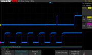
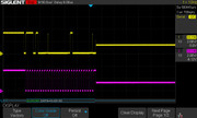
Zoomed out:

Zoomed in:

10)I2C signals (as measured on the BeagleBone pins) go OK until they hit a multiplexer channel that is connected to the bioreactor. At this point, both the SDA and SCL lines will get stuck around 1.7V.
Zoomed way out (note that the signal goes from the usual 0-3.3v, then gets stuck at 1.7V for a while, then goes down to almost, but not quite zero):

Zoomed out:

The moment everything goes wrong:

11)Once the multiplexer is connected to a channel with the bioreactor, any attempt to read/write to the multiplexer will fail e.g.
i2cset -y 2 0x74 0x00 0x01Error: Write failed, as long as it is connected to a channel containing a bioreactor. If the cable is removed, it will recover, e.g. i2cdump -y 2 0x74 will work. If a different channel is selected and the cable is reconnected, then everything is fine again.12)The temperature sensor at 0x1b is not affected until the multiplexer is connected to a channel with the bioreactor. After that, it displays the same symptoms e.g.
i2cset -y 2 0x1b 0x00
Error: Write failed.13)On the “Laser Measure” board, the resistance between SDA & GND (and maybe SCL & GND? I can’t remember) is ~300 ohms. I measured it multiple times, with multiple ohmmeters, in both directions. That seems very wrong. SDA & SCL to 3.3V are something like 10k ohm IIRC.
14)Disconnecting the 5 pin cable that connects the “Side Board” to the “Laser Measure” board, prevents the 1.7V lockup issue from occurring. I haven’t been brave (foolish?) enough to attempt powering the bioreactor with this cable disconnected.
15)Yzhang reported unusual OD measurements leading up to the failure.
All of this, particularly points 13-15, point towards some failure on the “Laser Measure” board.
If you’ve got any tips on how to narrow it down to a specific component, which I would then replace, I would appreciate it very much. It can’t be worse than the TSSOP-24 multiplexer that I swapped for no reason ;P
Thanks for your time, and sorry about the giant wall of text.
-
AuthorPosts